How does the Starer Relay coil get power?
Posted: Wed Aug 26, 2020 8:21 am
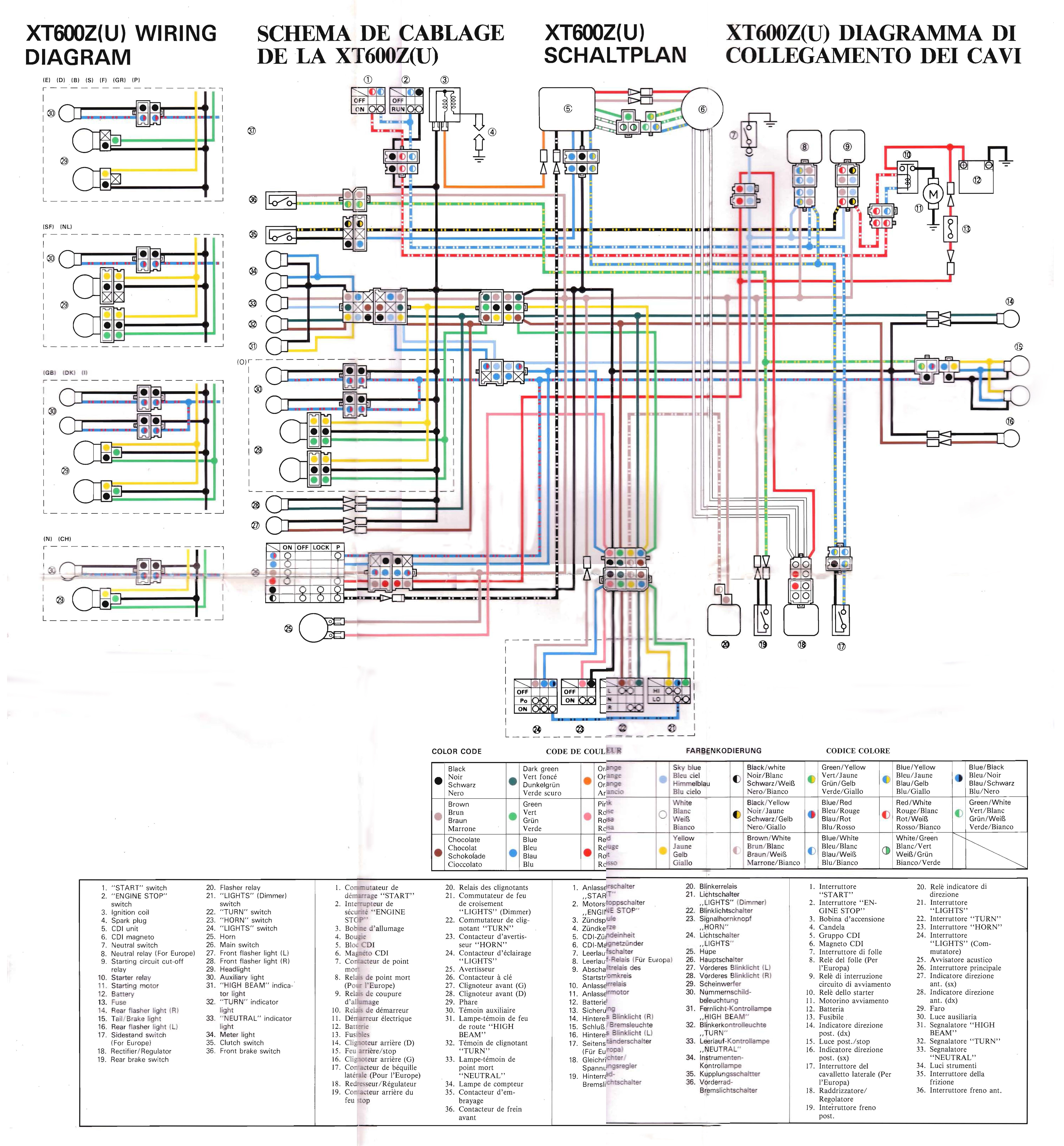
The circuit diagram below was photoshopped from several files from this forum (thanks Mezo). Its a big image 10MB and can be downloaded directly from http://easyonlineweb.co.uk/images/3AJ%2 ... iagram.jpg if anyone wants to.
I can't figure out where the starter relay (10) coil gets a positive supply from. I can see that the bottom end of the coil is connected to earth through the engine stop switch (1) and start button (2). The top end of the coil (where we need to get power to) goes through the starting circuit cutoff relay (9) then through the clutch switch (35) to the CDI (5) on the blue wire.
I thought that the CDI was powered from the alternator via the Red and Brown wires, and has no connection to the battery. So how can it be providing power when the engine is not running??
The starting circuit cutoff relay operates as long as the ignition switch is on, and the bike is in neutral (switch 7) - so no problem there.
But I just can't figure out how the positive supply to operate the starter relay coil gets there. This is driving me crazy!! Please help
I can't figure out where the starter relay (10) coil gets a positive supply from. I can see that the bottom end of the coil is connected to earth through the engine stop switch (1) and start button (2). The top end of the coil (where we need to get power to) goes through the starting circuit cutoff relay (9) then through the clutch switch (35) to the CDI (5) on the blue wire.
I thought that the CDI was powered from the alternator via the Red and Brown wires, and has no connection to the battery. So how can it be providing power when the engine is not running??
The starting circuit cutoff relay operates as long as the ignition switch is on, and the bike is in neutral (switch 7) - so no problem there.
But I just can't figure out how the positive supply to operate the starter relay coil gets there. This is driving me crazy!! Please help


